A puzzle game that makes us build a complete computer
If you should happen to be interested in how to turn an abstracted version of basic electronic circuitry into a puzzle game, read on.

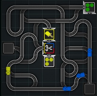
My favorite casual computer games are puzzles that allow me to pore over the solutions for hours. I want lots of little things to go whirr! and click! and then do my bidding. If you have not played Trainyard yet, I strongly recommend checking it out! (You can start with the free edition, Trainyard Express, which thankfully does not have any advertising or in app purchases, by the way.) Trainyard lets you draw tracks with your finger, and little locomotives are traversing them in funky patterns, changing their colors on the way, before either crashing or finding their destinations.

Trainyard is in principle Turing complete (i.e. you could build a computer in it), but Trainyard’s playing area is limited to 7x7 fields, and you cannot place any of the interesting stuff yourself (like replicators and color changers), so practically, that’s not possible.
On the other end of the spectrum, there is Minecraft, the famous open-ended, almost infinitely large brick-laying playground. Among other things, Minecraft is a three-dimensional cellular automaton, with a playing field that is 30 million cells wide and deep, and 255 cells high. Cells may interact with each other up to a distance of 15, with most of the interaction limited to the directly adjacent cells. Using specific materials that act as conductors, isolators, switches and repeaters, players can wire up their virtual fortresses with button-operated trap-doors and lighting. And some relentless players have figured out how to build computers in the game.
Building blocks
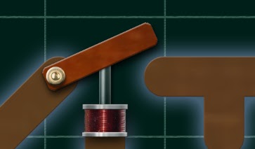
Building actual CPUs and computer circuits is a similar puzzle, and I liked it a lot as a beginning student of computer science. The classes started with an introduction to electrons jumping between holes in semiconducting materials, and how to trick these materials into forming diodes, transistors and so on. It is not extremely difficult to understand how a transistor works (here is the best explanation that I just found), but when we build circuitry with transistors, we will also need to amplify and dampen their outputs, and understand their interaction with capacitors, resistors and so on. Too much fluff before getting to the fun parts! After all, for your purposes, a transistor is just a powered switch, i.e. relay. A relay is an electromagnet that pulls or pushes an electrical switch to open or close a circuit in pretty much the same way as a finger turns a light switch. It does not get much easier than that. (Relays may be simple to understand, but of course expensive, bulky and slow when compared to transistors, which is why we don’t use them in actual computers.)
So, what we need are power sources, indicators (for instance, lamps) and powered switches. These must be connected with wires (including branches and bridges), and separated by insulators. We can probably use unipolar power, i.e. ignore the flow of electrons back from electrical loads (we can imagine that there every load is automatically grounded).
Cellular automata?
Should our simulator be a cellular automaton? Wireworld is a pretty nice one. Like Conway’s “Game of Life”, it uses only the immediate neighborhood of cells that are organized in an orthogonal grid. Unlike in “Game of Life”, there are not just two states, but four: insulator (i.e., empty), conductor (i.e., wire), “electron head”, and “electron tail”. In each step, the cells transition: insulators remain insulators, wires become electron heads if they are adjacent to electron heads, electron heads become electron tails, and electron tails turn into wires. These simple rules ensure that electrons seem to travel along wires. Branches of wires allow interesting things to happen: they may split electrons, to create power sources (usually loops that emit electrons in regular intervals), or cancel out electrons that meet each other head-on, which allows the creation of diodes and logic gates. Wireworld is powerful enough to build computers in it, but it’s a tedious process. Also, the “electrons” do not travel along a voltage differential, and the similarity to actual electronic circuitry is quite superficial.
Basic principles
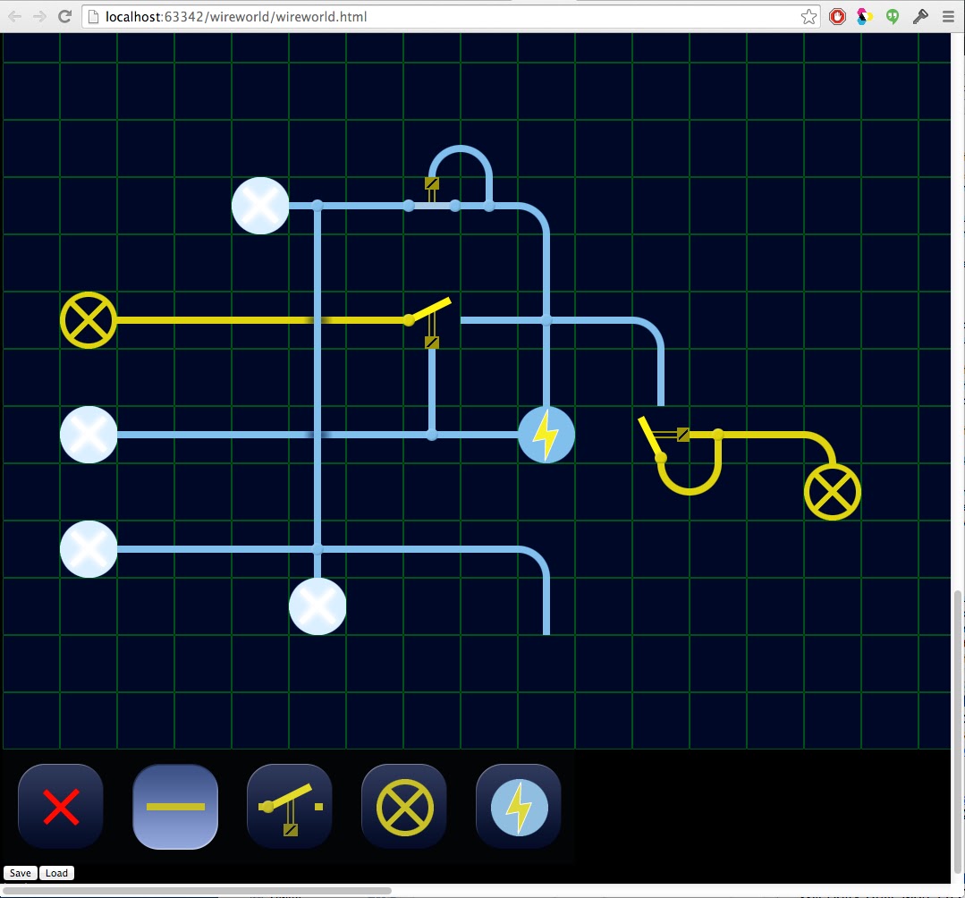
Here is my first prototype idea. We will use an orthogonal grid with conducting and isolating cells, but in each step, we let the electricity flow from the power sources instantaneously through all connected wires (i.e. not just to the adjacent cells). If electricity hits the solenoid of a relay, its switch should be in one position, if not, then in the other. (I.e., the impulse does not toggle, but make the difference between on and off.) We should have two kind of switches: those that turn on when powered, and those that turn on. Because of the order in which the cells will be calculated, we won’t be able to guarantee that the switch has already been turned into the correct position when it is asked to pass on a signal, so we determine the new switch positions at the end of each cycle, and switch conductivity will always reflect the switch state of the previous cycle. Consequently, switches need to remember their state.

Our assortment of parts cannot trap or store electricity. No capacitors means no DRAM. Memory cells need to preserve some kind of state, which will have to take place in the switches: a switch can turn on another, which will connect it to a second power source. The switch can remain in the on-state even if the original signal is gone, so we should be able to build Flip Flops and something looking like SRAM circuits.
Assets
My first prototype is going to be a little hack in Javascript/jQuery. I will make a little 5x5 cell drawing that contains all the possible wire edges for a north/east/south/west neighborhood grid: four corners, horizontal and vertical lines, four T-shaped crossings, a cross shaped crossing, and a bridge (two wires that cross but are not connected). Then we will need powered versions of all of these (with separate versions for bridges that are only vertically or horizontally powered). There are four possible directions for the switches, each with two switch states, and each of these eight variants comes in a powered version, too. Finally, we need active and inactive lamps and power sources. Thankfully, we do not need to slice this drawing into sprites, because we can simply select the desired portion of our graphics file by treating it as a CSS background.
I have defined each cell as a div with fixed width and height, and a class that determines whether it is powered or unpowered, or what state the respective switch is in. By giving a click event to each cell, we can attach a simple UI that allows us to draw our first circuits.
Later, we should make it nicer, by giving each cell a foreground and a background layer, and drawing the overlapping backgrounds first. This way, wires can have rounded end-caps, switches can have drop shadows, powered wire segments can extend into the fields of unpowered switches, and powered wires and lamps can glow beyond their field boundaries (which they should, because their non-glowing parts must already be placed directly at the boundaries).
The User Interface
For a start, we can use an interface that switches between modes. At each time, one mode is active and determines what happens when we click into a cell: “erase” deletes content (i.e. produces an empty, insulating cell), “wire” draws conductors, “switch” places a relay, and “lamp” and “power” do what you expect. Wires are internally stored as a cell that connects to all neighbors, but they are displayed as corners, strips and crossings, depending on the configuration of their neighbors. Whenever the user updates a wire (i.e. inserts or deletes a wire cell), we look at its neighbors and update accordingly. By clicking on a fully connected wire (i.e., a cross shaped wire), the user can toggle between wire and bridge. Since switches always have three inputs, we can determine their orientation from the surrounding wire configuration, and will update it on the fly whenever that changes. By clicking on an existing switch, the user can toggle it from a circuit-closer to a circuit-breaker (i.e. determine whether powering it will flick it into the on position or off position).
I found that I change between the modes for wires, switches and erasure a lot. Let us do something about that! We can make the “wire” mode the primary one. With a single click, we add or remove a wire cell (except if it is a cross). With a double click, we insert or remove a switch. Voilà! Let us hope that this will work on the iPhone, too. In the final game, we probably want to fix the positions of lamps and power sources anyway, and only let the user edit wires, bridges and switches.
The simulation algorithm
We could calculate the spreading of electricity by treating our world as a cellular automaton, but that would be quite slow, because we would have to repeat the evaluation for as many cycles as there are cells in the longest wire. A better alternative traverses the wires recursively, starting from each power source. All cells that we encounter become active, all others remain inactive. If we hit an active cell, we must have already visited on a different route, and we can abandon that branch of the recursion. If we hit the solenoid side of a switch, we check if was powered in the last cycle, too, and if not, add it to a list of switches to be toggled at the end of the current cycle. Finally, we need to check for all switches that were powered in the last cycle, but receive to more power in this one, so they can be toggled, too. This simulation algorithm has no trouble to calculate a circuit of 100x100 cells for several times a second in my browser.
A first optimization
If we want to build large circuits, with millions of cells, we will probably run into problems with my simple algorithm. It is a good idea to exploit the fact that connected wire cells share the same state, so we can segment the our world into larger objects, and perform the calculations only for the each object. The segmentation can take place each time after the user performs a change. It runs recursively along the wires and breaks up at the switches. Each segment is defined by:
- a set of wire cells and lamps
- a set of horizontally connected bridges
- a set of vertically connected bridges
- a set of switches that it can power
- a set of switches that it toggles
- a set of power sources and switches it can by powered by
- its shared state in the current cycle (powered or unpowered)
In addition, switches remember whether they are currently in the on or off state.
During each cycle, we start from the list of power sources, and call all connected segments. Each segment will check whether is is still unpowered, and if yes, turns into the powered state. It then tells all switches that it toggles that they should consider themselves be powered in the next cycle, and for each switch that it powers, checks if had been turned on in the previous cycle,
Some simple stuff
Conductors conduct, power sources power, lamps light up, and switches switch. How rewarding! Now let us re-create some of the things I did with relays when I was a kid. What about a relay that turns itself off as soon as has been powered on? What about a bell, i.e. a relay that flickers between on and off? Let us build a cascade of these, so we can get a slowly flashing light… Here is a seven-segment display. Can we light up some parts but not others? Fortunately, our relay can also act as diodes. If a wire powers both the solenoid and the input of a switch, it can turn on its output, but the output won’t be able to turn on its input! Switches are natural AND gates. But for a NOT, we will need a secondary, always-on power source. Ah, there we go: a full set of logic gates.
First observations
Building circuits with the prototype is a lot of fun for me. I find myself poring over how to address a bunch of lamps forming a complete seven segment digit display. And once that is done, how can we build a counter? And turn the whole thing into a watch? But perhaps that is just me. The first test subject is four years old. It has just spent half an hour with my prototype, and seems to be extremely satisfied when it manages to turn on new lamps…
Thinking about level design
Turning this into a game will require a progression of levels. A level will have a starting state with some immutable cells, and is solved as soon as the user has created a certain final state. The final state can be defined by a (often dynamic) configuration of lamps. To indicate the desired final state, we can let the background of the lamps flash in the target configuration. Lamps that are lit up in the wrong way should turn red. Thus, we will need some degree of background customization, to indicate editable and immutable fields, as well as target configurations.
Initially, the levels should teach the user about the principles of the simulation and start with small, non-scrolling playing fields.
- Connect a power source to a lamp
- Connect a power source to two lamps
- Connect a power source to one lamp, but not a second one
- Connect two alternating power sources to a lamp so it is lit continuously
- Connect two alternating power sources to two lamps so they flash in the right order
- Do the same with bridged wires
- Do the same with an AND connection (i.e. use a switch)
- Invert a signal (NOT)
- Let a lamp flash whenever one of two power sources is active, but not both (XOR)
- Let it flash whenever one or none are active (NAND)
- Let it flash whenever two or none are active (NOR)
- Build an oscillator from two switches
- Cascade oscillators to get a low frequency
- Build a Flip Flop
- Build a memory cell for one bit
- Connect two alternating power sources to two alternating patterns
- Do the same for patterns that shared some lamps (i.e. use diodes)
- Power two alternating digits in a 7 segment display
- Power all 10 digits in a seven segment display
- Power all 10 digits in a seven segment display with 4 input sources
- Build a memory cell with four bits
- Show the contents of a memory cell on a 7 segment display
- Alternate between the contents of two memory cells on a display
- Show the contents of one 16 memory cells on a display
- Connect two seven segment displays to form a counter to 99
- Build an 8 bit memory cell
- Show the contents of an 8 bit memory cell on a two digit display
- Build a half-adder
- Build an adder
- Build a counter
- Build a display that runs to 59 and then goes back to 00
- Build a watch
- …
Beyond
Minecraft computers demonstrate that there is no limit to what some people will do: they require many hundreds of hours in research and build time. However, most of us have a limited endurance for repetitive tasks. If we want to go beyond 7 segment displays, perhaps we will need macros, i.e. reusable complex components. With macros, it should be feasible to do things like
- fully addressable memory banks,
- a memory controller,
- a small dot matrix display,
- a CPU with program counter and registers,
- an ALU with addition, multiplication and subtraction,
- a machine language with conditionals and branching execution.
A simple way of introducing macros would be the explicit reuse of contents of earlier levels. Because we made sure that user input has to conform to particular specifications, we can treat the results as logic gates, adders, half-adders etc. We could pre-define the structure of the final machinery and then automatically fill it with replicas of the user-defined solutions for memory cells, logic and display circuitry. However, such a predefined solution deprives the user of the joy of building their own computer. I think I would prefer a way of defining macros explicitly, by offering essentially two different simulator UIs. One lets us create components (macros), such as gates, memory cells and flip-flops, on small square boards with well-defined outputs and inputs. Whenever we solve one of the intermediate levels, the level turns into a microchip. In the later levels, we get an infinite board and a toolbox with already completed microchips and are allowed to use these instead of wiring everything by hand. This does not only make things easier for the user, but also for us, because we can make the simulation much more efficient. Since the microchips are not “free-form” but conform to exact specifications (the level solutions), we can replace their circuitry by program code.
Does someone have a little time to get it done?